DeskMCâ„¢ HD

Posted 10 years, 10 months ago    7 comments

Here's some pictures that have been maturing for a couple of years, I think it's about time they were posted. These machines were built to order for some very patient customers. Travels ~330 x 230 x 230 mm XYZ, brushless servos and ground ball screws all round, on THK caged ball linear bearings, running Granite Devices VSD drives.

Pardon the mess...


Electronics enclosure - front


Electronics enclosure - back


Improved Z axis chip protection


New back panel


New, larger electronics enclosure


Michael's mill - back.

Front.


With way covers - front

Back


The Bench Top Mill build - part 1: The base.

Posted 14 years ago    28 comments

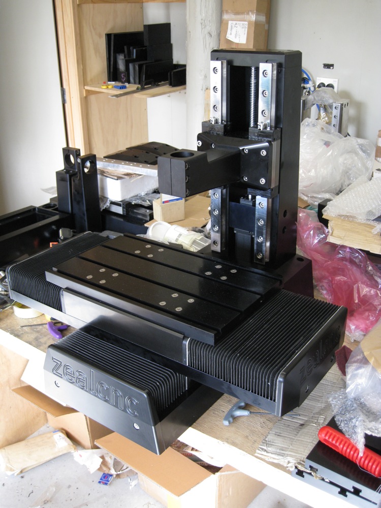
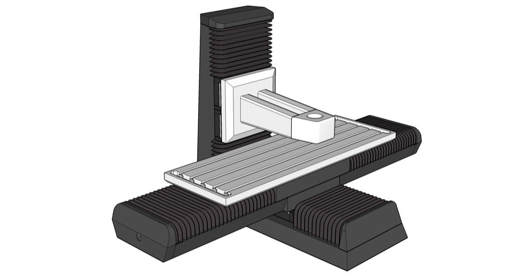
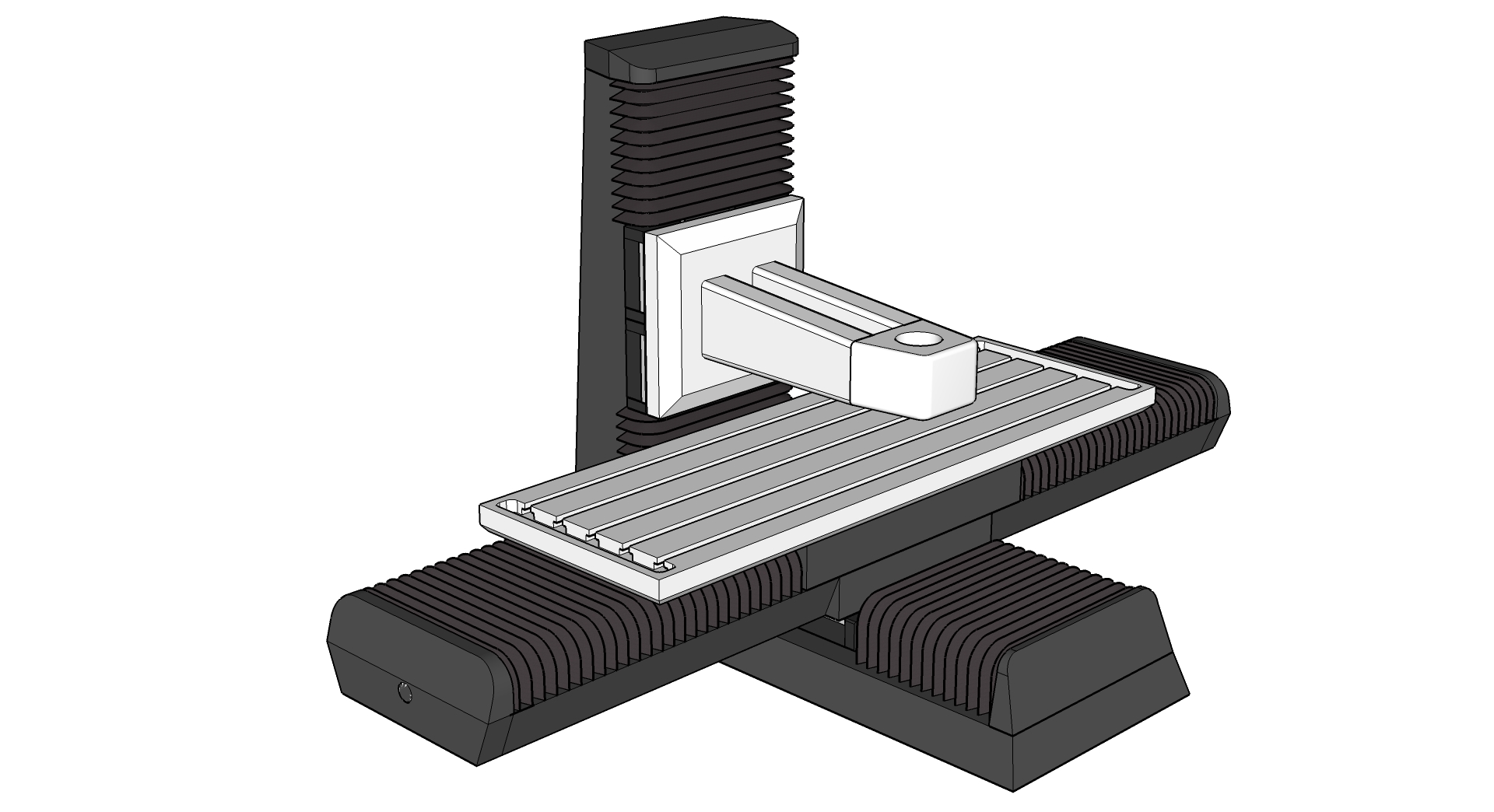
Here we're starting the build log for the Bench top mill. A quick recap on the spec and goal:

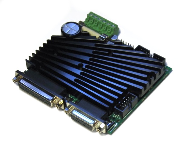
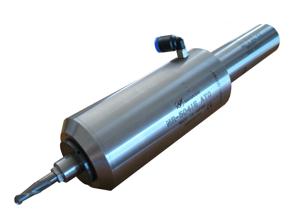
Travels will be roughly 750 x 400 x 400 mm (30 x 16 x 16"). Ball screws are C5 grade ground NSK items, 25 mm dia. and 8 mm pitch. Axis drive motors will be 300 watt brushless servos, driven by Granite Devices VSD-E drives. Feed speeds ~ 500 ipm, resolution .002 mm (0.00008"), Spindle to be confirmed. Frame will be constructed from square section steel bar.

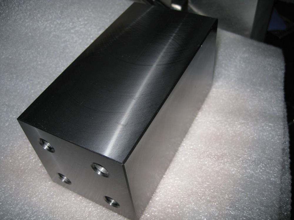
The first part - front cross member and Y axis ball screw floating end bearing support. Milled from 3" square bar stock, the important thing with this part is to ensure the ends are parallel, since the side rails mate with the ends of this part.

A 3.15" 45⁰ insert face mill does a nice job of chamfering the corners as well as facing the sides and ends, and leaves a nice surface finish for this part.

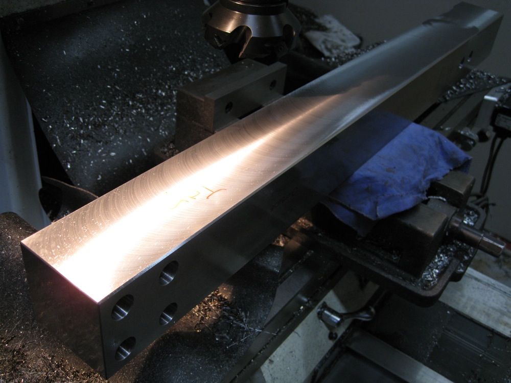
Next: The side bars that will carry the Y axis linear bearing rails.

One side done. You'll notice there's no milled rebate for the linear rails yet. That will be cut later, the base will be assembled and machined as a single unit to ensure all critical surfaces are parallel and co-planar.

As this part was longer than the travel of the mill, it had to be machined in two steps. Much care was taken to ensure all surfaces are square and parallel - more work for the 3" face mill. The steel stock is behaving very nicely, with no evidence of any bow or twist so far, and it machines particularly well.

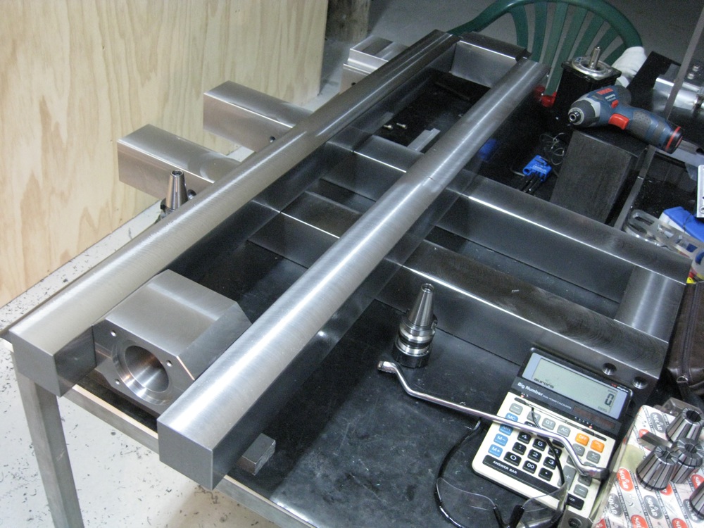
The Servo/Ball screw mounting block is done, and that completes the basic parts for the machine base.

Next job for the base will be to fix them all together and cut the slots for the linear bearing rails, drill the column mounting holes, and drill and tap for the bolts that will fix the linear rails in place. There will also be some tapped holes in the bottom of the base to allow for fixing to the stand, and fixing points for the limit switches and way covers...

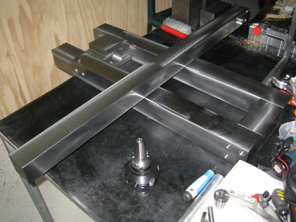
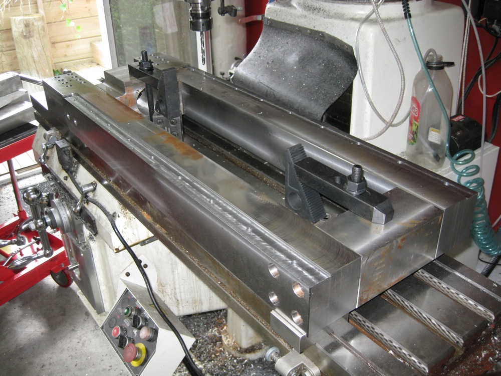
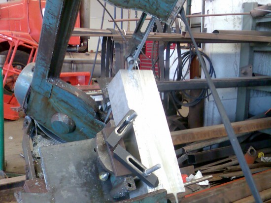
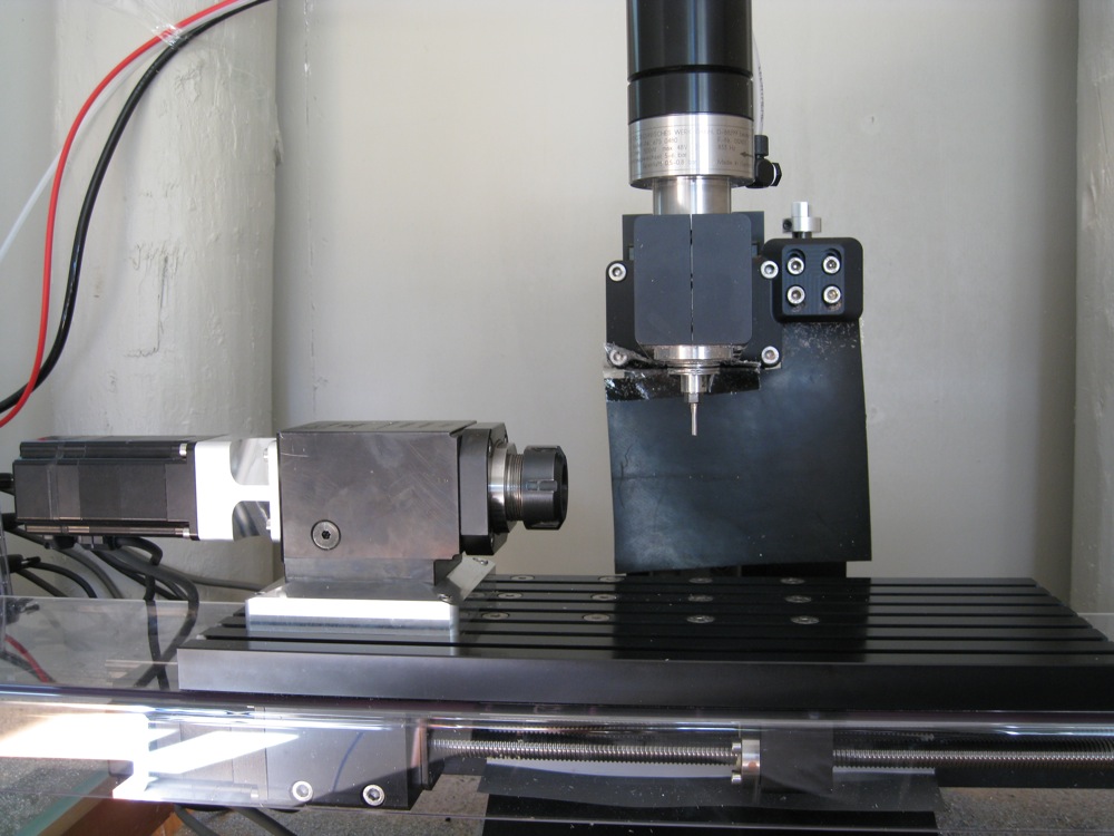
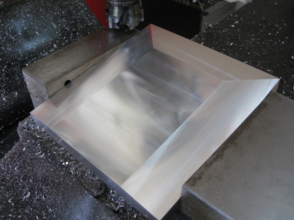
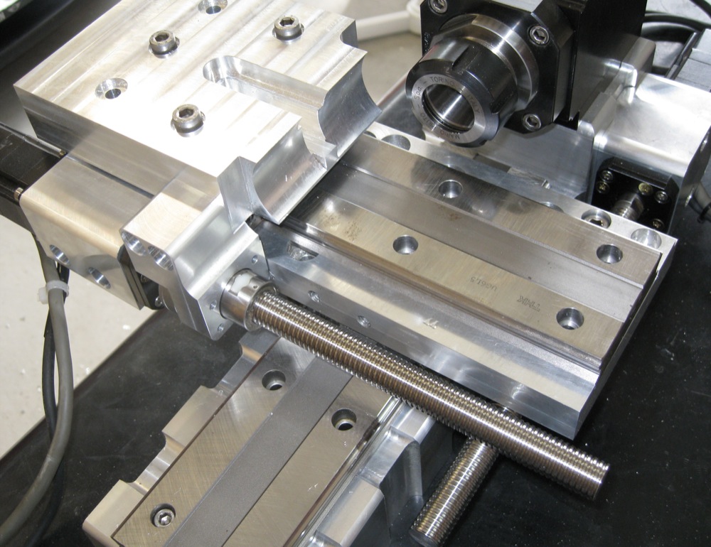
First though, a start on the saddle assembly. The new part is one of the two longest jobs for this build, and I wanted to get it underway in case I was unable to get it acceptably accurate over the full length - in which case it would have had to go to an engineering shop with a bigger machine. Fortunately it went well. I used a dial indicator, and with the turret on the big mill rotated 30º I tested the movement of the table as it traversed with the stock mounted. After firmly locking the Z and Y axis, I was able to confirm the X axis was staying very close to level through the full travel, so I went ahead and faced the sides, chamfered the corners and trimmed the ends.

The 2.5" square (63.5 mm) stock has a finished size of 62.5 mm square, so there wasn't much to come off this time. I drilled and counterbored the holes for the cross member (far end in photo, will also house the ball screw's floating end bearing), but left the holes for the servo/fixed bearing mount for now as I need to assemble the mount onto the screw and measure the exact length of the assembly first.

I've now tapped all the threaded holes in the parts so far: after some hesitation I used my thread forming taps. If you're not familiar with these, then you owe it to yourself to check them out. Looking like a normal tap but without the flutes, the thread is formed through metal displacement, essentially a forging process. This has a number of significant advantages: no chips collecting at the bottom of blind holes, no need to back the tap up to break off the chips, and the thread formed is apparently significantly stronger. They are also self-centering to a certain extent. The caveats include needing a precise hole - the diameter must be just right, too small and the tap will bind and break, too big and the thread formed will be too shallow. A good tapping compound is absolutely essential. For the smaller taps I drive them with a cordless drill - very fast, since there's no need to back it out to clear the hole. For the larger threads I use a normal tap handle, but it's still much quicker than conventional taps. My initial hesitation was due to having broken one recently in cast iron - all my other work with them has been in aluminium and I wasn't sure how well they would work in this grade of steel. As it turned out, I needn't have worried - they worked beautifully, and left a very nice result.

Here's a picture of the difference between standard and forming taps - standard on the left, forming on the right. You'll notice some fine grooves running the length of the flutes on the forming tap: these let the tapping fluid escape when tapping a blind hole. There's more reading Here.

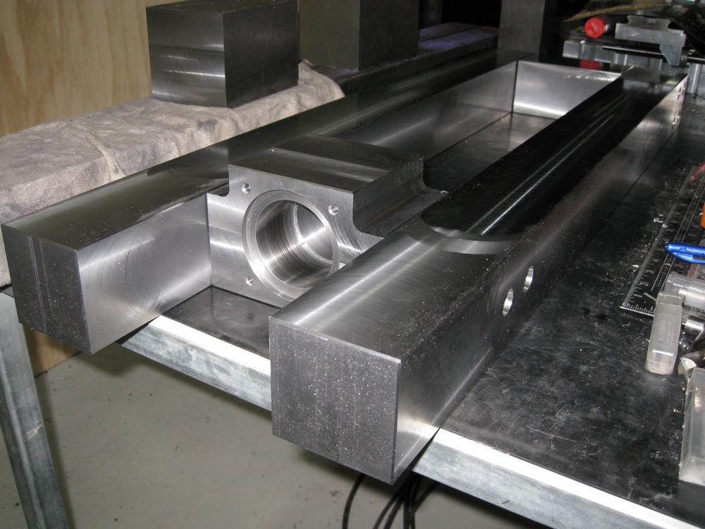
Today I chose to make a smaller part after all the heavy lifting of the last few days! This is the end bearing support for the X axis ball screw, which also serves to stabilize the end of the bars that will support the X axis linear rails.

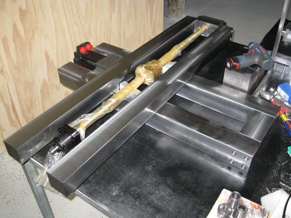
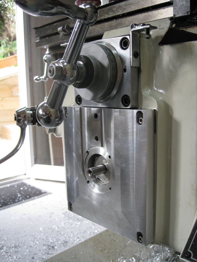
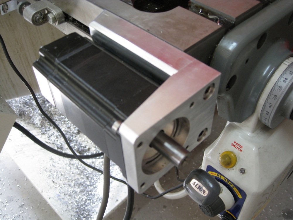
I fitted a Nema34 servo to the Y axis motor mount, and dropped the X ball screw roughly into place, just to confirm things were fitting as they should.

Next up, the X axis servo/ball screw fixed end mounting block, followed by the column. I'm looking forward to having the column done - it'll start to look more interesting then, I think!

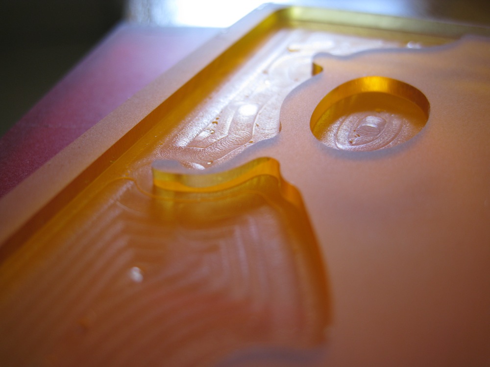
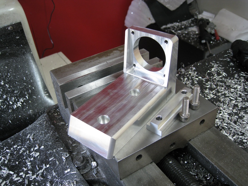
Here's that ball screw mounting block - it still needs the other side bored out for the ball screw fixed end support, which houses the dual angular contact bearings that fix the screw in place axially.

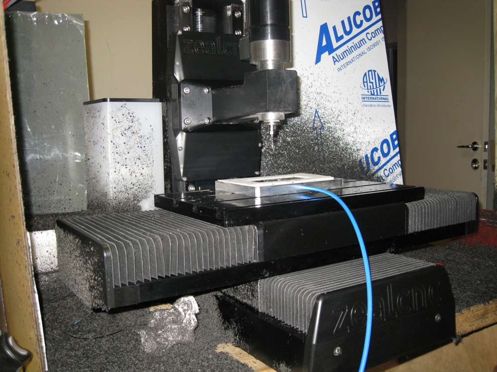
Lots of hot chips today!


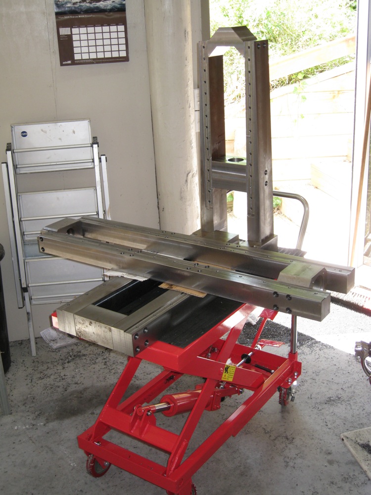
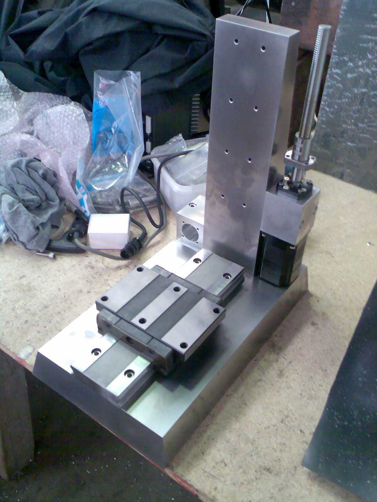
After something of a hiatus, at last there is some progress to report! I need this machine to make some stuff now, so it's underway again. Some parts went a bit rusty, and we have a couple more parts done:

My brother has kindly stepped in to help. The two chunky parts with no rust on the lower right are his first ever machined parts - pretty good, I say!

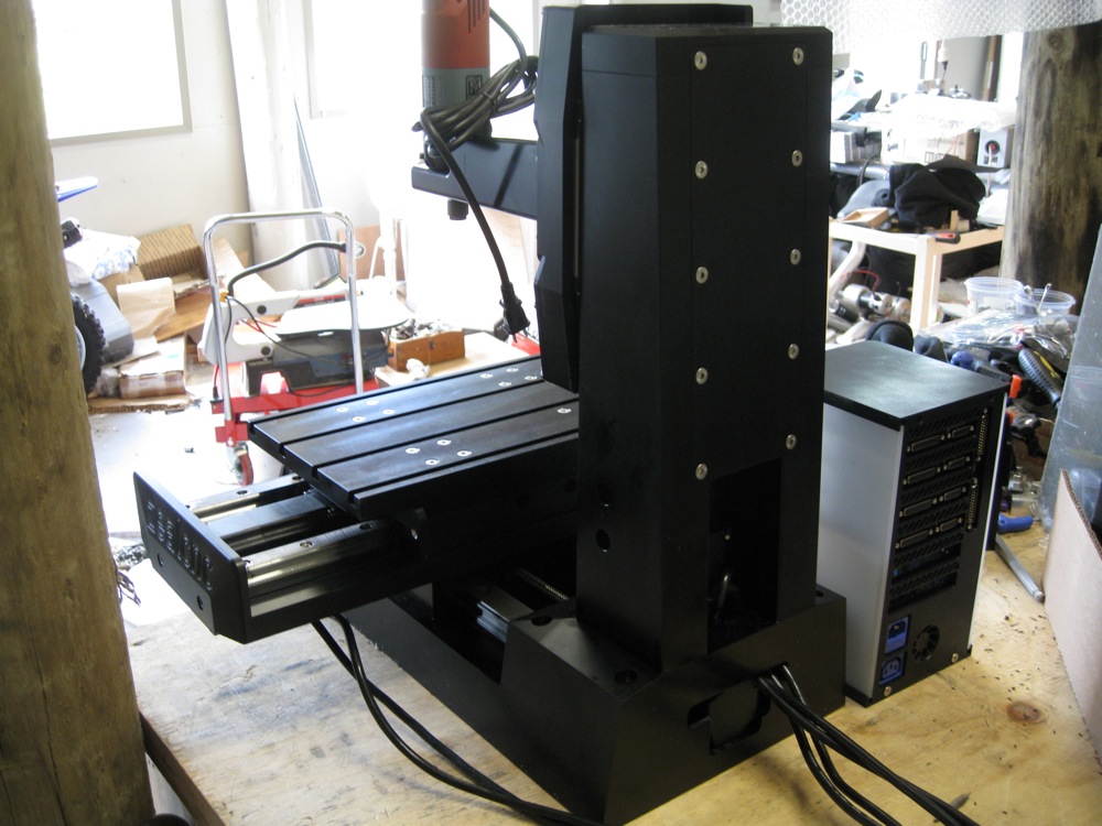
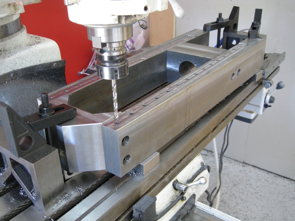
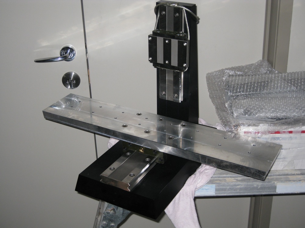
The base assembled on the mill, rebating and drilling for the linear bearing rails.

...and same for the X axis.

... and the Z axis. For each of those, we dialled in one long side on the mill table, then clamped it down and bolted the rest of the parts to it, with 123 blocks under each component to accurately locate all parts co-planar.

With the bolts in the assembly just snug, we clamped the rest of the parts down and tightened the bolts up before milling the rebated pads where the linear bearings seat. Each pair of bearings will have one rail clamped against a reference edge, then the other rail will be aligned to that one with a dial gauge.

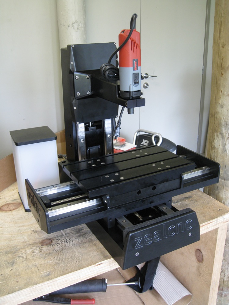
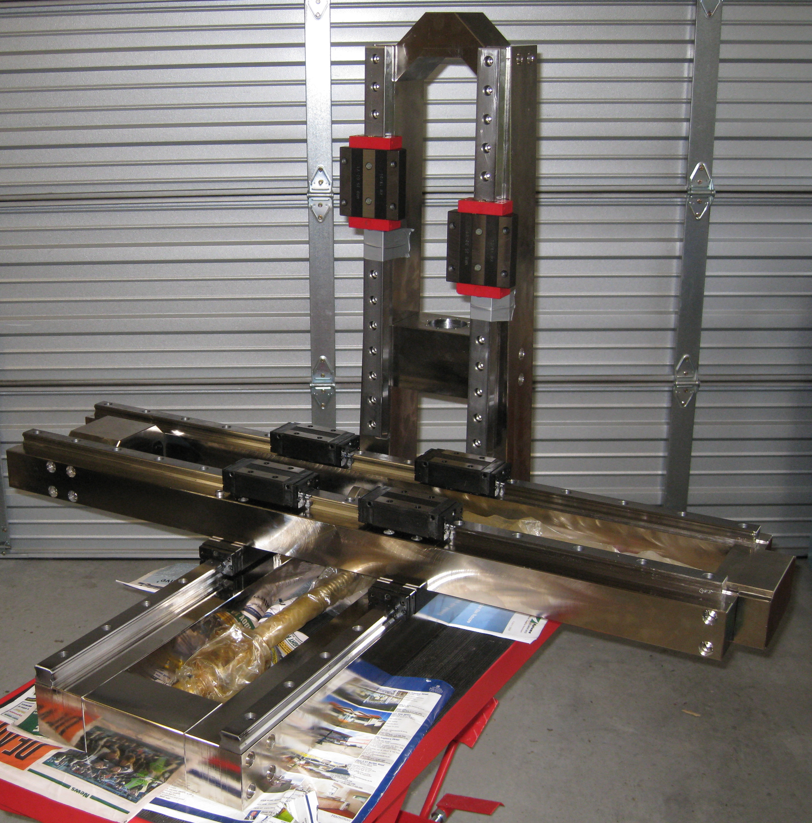
Let's call that the end of part one. Still to come - Assembly, Stand and enclosure and Electronics!
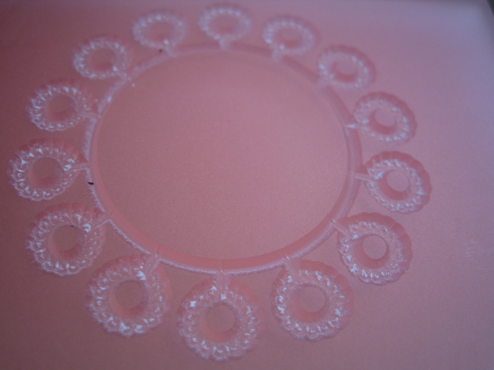
One more pic.


A new desktop mill

Posted 14 years, 3 months ago    8 comments

Just so you know I'm still here! This machine was started quite a while ago, but since it's twin had moved on to a new home, I decided it was time to finish it off and use it to test some new ideas.

Cutting the column, from 4" x 5" aluminium plate.

The base and column together, Y axis rail and Z axis servo/ballscrew assembled, just for fun.

Base and column anodised, X axis coming along...

Assembled, with Granite Devices VSD-XE servo drives and the power supply.


First cut, just a simple pattern to make sure it works. Circles on circles on a circle... 

And the end result. The cutting tool I used is coated, designed for hardened steel it is definitely not ideal for acrylic, and left a mess at the bottom of the cut but nevertheless, a successful first try.

Making a small vacuum table.

Here's the finished unit. The plumbing will inevitably be changed around once I work out a tidier layout. I wasn't sure what gasketing to use, the 1/4" round type was a bit tight in the slots, and I had trouble getting it to seal. I'm currently using a venturi type vacuum generator, which works well enough, but doesn't supply much volume - a proper vacuum pump is on the way, which should work much better. After seeking advice from a friend, I found that I should be using a rectangular section gasket. It's working well now, looking forward to a proper test!

...and here we go:

It works, very well. Much faster than screwing or clamping!


Trying out new types of cutters for acrylic - with a little experimentation, we're getting a very nice finish on the vertical edges:

I've added a nice, solid fourth axis! 'Borrowed' from the micro lathe, it's strictly for < 50 mm or 2" diameter work in softer materials, or < 25 mm or 1" diameter for metals. It has automatic homing on power up and zero backlash, and should also enable the machine to be used as a mill/turn machine with the addition of some turning tools. Hoping to get a chance to try it out very soon!


Knee / Turret Mill CNC Retrofit

Posted 14 years, 11 months ago    13 comments

I started a CNC retrofit of my manual mill today. The Chevalier FM3-VK is basically a 10 x 50 Bridgeport clone, very well built and accurate, generally a very nice solid machine. It has a 3 Hp spindle motor with a variable speed drive, and takes NT30 or BT30 taper tooling (there's a handy drawbar spacer to allow use of the longer NT30 shank, hidden under the head of the drawbar).

When I purchased it, it was wired for 415 volts, 3 phase, and I only have 230 volts, single phase power available in my workshop. The spindle and coolant pump motors are dual voltage, so we swapped them to the lower voltage setting and hooked up a couple of VFD's to drive them, taking control signals from the existing switch gear - for all intents and purposes, it operates just as it would if it were connected to 3 phase power.

As I'd intended to keep this machine manual, I've fitted an Acu-Rite DRO, which will be somewhat redundant once the retrofit is complete. I'll likely leave it fitted, as it will be nice to have should I ever want to use the mill manually for the odd small job. My preference would have been for direct drive servos, however the motor sticking out the end of the table on the X axis would have come very close to the wall on that side. Accordingly, I'll be fitting the brushless servos with belt reduction to drive the screws on the X and Y axis so that I can turn the servos around, and a direct driven, fine pitch ball screw will operate the quill. The knee will remain manual for the time being. Initially, I'll be retaining the existing axis screws too, as this series of Chevalier mills has adjustable dual nuts for the X and Y, which can be tweaked to reduce the backlash to as low as .02 mm (0.0008"). A change to ball screws in the future is likely, but the timing will depend how well the existing trapezoidal screws work!

One of the goals of this conversion will be to keep the machine to it's existing footprint - no motors sticking out the front or side, as there's limited space as it is. The mll must stay operational during the upgrade, as I use it daily. I'd also like to avoid drilling or otherwise modifying the machine itself, and as I quite like the look of the machine, I'd like this upgrade to be aesthetically pleasing as much as possible too.

So, starting with the Y axis: I'll place the servo inside the knee, and the belt drive pulley will replace the graduated dial under the hand wheel. Conveniently, the kind people at Chevalier built it with an access hole in the front of the knee, so I'll use that, thank you! 

Cutting stock
Cutting stock

I cut a piece of 25 mm plate to form the motor mount...

Milling the edges square

...then milled the edges square...

Bevelling...
Bevelling...

...and beveled the sides and bottom while I had the face mill fitted, for purely aesthetic reasons. I had to remove the jaws from the vise, as the plate was otherwise too big to clamp at 180 mm x 191 mm. As I wanted to be able to adjust the belt without having to access the back of the servo up inside the knee, I slotted the holes where the mounting plate attaches to the knee instead. After boring the hole for the servo mounting boss, the back of the plate is pocketed to take the square servo face plate, and 4 x M5 tappings take the stainless SHCS bolts that hold the servo in place. The face of the plate is relieved to give clearance for the pulley and belt, and a couple of threaded holes will give an attachment point for the protective belt drive cover.

Y axis motor mounted

My calculations suggest these servos with a belt reduction will be able to drive this mill just fine, however if I'm wrong, I've left enough clearance to switch to larger motors later.

Next, the X axis. The servo will be mounted using the 'T' slot on the front of the table. I'd have preferred this motor be mounted at the back of the table, but then it could hit the column and would reduce the work envelope slightly.

X axis motor bracket and mounting hardware

The bracket attaches to the table using the long 'T' nut. The bore is a snug fit on the motor mounting boss, and another 4 x M5 SHCS fix it in place.

X axis motor mounted

The top of the bracket is flush with the top of the mill table so it won't impede larger work.

Next, the Z axis. I've been looking at making the knee the Z axis, but that would be difficult without removing the knee and I don't want the mill out of action, so for now I'll continue with the plan to use the quill.

More to come soon...


Granite devices Servo drives - significant new feature!

Posted 15 years ago    3 comments


We have some very exciting news, I believe it will have significant implications for many CNC machine builders:

Granite Devices' VSD-E and VSD-XE are also designed to drive two independent axis with one drive using DC servos.

This means you could build a lathe with only one drive! Or a 3 axis mill or router with a DC servo spindle motor with 2 drives. How about a 4 axis machine with two drives? Many routers use dual motors for the long axis - you could drive both with one drive, and another drive for the Y and Z axis.

Now for a similar price to stepper systems, you can have the speed and power of a servo setup, and no more lost steps.

This new functionality will be implemented by way of new, free firmware - all existing VSD-E and VSD-XE drive owners can upgrade to the new firmware too. We're expecting this release very shortly.

You can order the VSD-E or VSD-XE at our shop - www.zealcnc.com

We're also offering free worldwide shipping on all servo drives until the end of March, so if you're thinking of buying drives soon, be sure to order before April!


The Micro Lathe

Posted 15 years ago    12 comments

This is a small lathe currently under construction, a basic prototype to test the theory and gain some hands on knowledge. It's work envelope is roughly 2 x 6", it has fine pitch ground ball screws and brushless servos for both the axis and spindle drive.

For it's size, it should be nicely solid, and will hopefully be capable of turning out some nice work. The tooling will be mounted along the front and side of the tool holder block (gang tooled), and there should be room for turning, threading, boring, drill, centre drill and cutoff tools. It'll be a tight fit, but with some optimization I expect it will work well.

The next stage will be live tooling to allow a greater variety of workpieces to be produced.

Once it's all working, I'll tidy up the design and look to building a larger version, with a view to eventually adding a turret also.

UPDATE:

The Lathe is almost ready. The electronics are wired up, the servos are tuned, and there's only a couple of minor details left before we can give it a try. We're waiting on half a flexible coupling for the X axis, and the way covers...

I made a short clip of jogging the Z axis and the spindle running, starts at 1 rpm then up in several steps to 4000 rpm. Nice and smooth, very quiet (the camera microphone makes it sound much louder than it is - you might want your volume down a little):

I also needed a set of spanners to close the collet chuck, so I made some on the desktop CNC mill (another loud video):


8 December 2009

Just realised I didn't update this page once the lathe was working. Oops... Here we go, first try in Stainless Steel:

Here's a video turning a scale model of an ISO tool holder:


It needs more tools and decent way covers, but they might have to wait for the next version :)


A slightly larger 'Benchtop' machine...

Posted 15 years, 1 month ago    11 comments

While we await information on parts availability for the first machine (to allow us to offer the best 'bang for the buck') here's a peek at a larger machine for the builder who needs more capacity. With full way covers for flood coolant, servo axis drives, and oversized THK linear bearings, this is another solid, durable machine.

This is stretching the definition a bit - travels on this machine are 30" x 16" x 16" XYZ (750 x 400 x 400 mm). As for it's smaller sibling, this is intended to be suited for high precision work using light cuts at higher feed rates, not heavy cutting.

Fast rapids are more important as the travels increase, and the larger X travel means a larger ball screw is desirable to avoid potential vibration or whipping at higher speed. This design calls for 25 mm dia., 5-8 mm pitch ball screws. These screws will give us slightly more force for a given motor torque than the 10 mm pitch planned for the smaller machine, enabling us to use the 70 mm frame brushless servos on this machine also. We will be using some ground NSK 25 x 8 mm pitch screws for our build, and we expect peak feeds in excess of 600 IPM or 15 m/min.

The spindle will again be interchangeable, this time we'll be building our own 2.5 Hp ER32 collet direct drive spindle which will be complemented by a 1.2 Kw, 50,000 rpm KaVo HF (high frequency) spindle.


Update: 

We've now started building this machine, and our version will be a steel one, rather than aluminium - after much consideration, it was decided that steel would be a better choice for a machine this size.

We've chosen a grade of steel we hope will behave well and remain stable without warping or twisting unduly, and will hopefully machine nicely also. The cost is similar by volume to Aluminium, but it should be much more rigid. The article covering the build is Here


First machine in planning...

Posted 15 years, 1 month ago    5 comments

The first machine for this website is on the drawing board. It'll be a desktop mill, based on the couple of prototypes already built. It's a solid, durable machine for it's size, and should be capable of excellent accuracy for making small, precise parts.


Basic specifications:

It will have a working envelope of around 400 mm x 250 mm x 250 mm (16" x 10" x 10"). Travels could be customized to suit the application or personal preferences of course, but this seems a useful, manageable size.

Axis motors could be either Servos or Steppers, but we will use the servos and drives from the ZealCNC shop. A Smooth Stepper USB interface will allow us to make use of the high speeds available with servos, without compromising resolution, and will also allow use of a PC without a parallel port to run the machine via Artsoft's Mach3 software.

Spindles will likely be interchangeable - a high speed brushless spindle complemented by a slower ER16 collet spindle with more torque.


High Frequency NSK E3000 spindle with pneumatic tool change


Sherline IPD spindle


Ball screws will be 16mm, for a machine like this a good pitch is 5 to 10mm. We'll be using 10 mm pitch - we'll be able to maintain some very brisk feed rates for a high speed machining strategy to match the high speed spindle, and our servos have the torque needed for deeper cuts with slightly larger cutters with the budget spindle.


Please feel free to ask questions or make requests or suggestions via the comments!


More Recent Posts

Build your own CNC Mill or Lathe!

Shim